
Flex PCBs
The flexibility of a flex circuit makes them more versatile than rigid PCBs, adapting to small or irregularly shaped spaces where standard PCBs cannot fit. They can also withstand the impact of vibrations and other disruptions within harsh environments such as satellite equipment, all while providing high conductor density. Flex pcbs are ideal for applications where downtime cannot be tolerated and the equipment must function when required, such as in life support items and flight control systems.
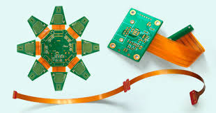
The basic construction of a single-layer flex pcbs uses copper foil pre-laminated to PI (polyimide) film, then etched and drilled. This is then laminated with an adhesive-based Polyimide coverlay that has been pre-punched to expose the copper pads. This is a very different process to standard rigid PCBs which use conductive epoxy to create the copper surface, but it offers the same functionality and performance as a rigid board.
A flex circuit’s ability to bend and flex means that there are some additional issues that must be considered during the design process, including the location of plated through holes and the use of stiffeners to reduce strain or vibration. Stiffeners are strips of rigid material placed on the perimeter of a flex or rigid-flex board and secured using acrylic thermally cured adhesives. They can increase strength, thickness and rigidity, as well as reduce bending strain and improve solder joint reliability.
Design Limitations of Flex PCBs
Keeping the copper area around the flex and bendable sections free of discontinuities is crucial for a successful flex PCB, such as avoiding stacking of traces within this region. This prevents stress points that can crack or fracture the flex and bendable areas of the circuit. Also, ensuring that all traces terminate at the same point on the flex and bendable portions of the circuit and following IPC bend guidelines helps to reduce stress and failure points.
For the same reason, a good flex PCB design will include the use of rigid material such as FR4, kapton or aluminum to add rigidity where needed. These are often added at the corners of the flex or rigid-flex section, where the circuit meets the rigid portion of the board. Stiffeners can help reduce strain, weight balance and vibration, as well as increase heat dissipation and strengthen solder joints.
In order to keep the assembly process efficient and cost-effective, flex PCBs should be arranged to minimize the number of connectors where possible. This is especially important for applications where the flex or rigid-flex section will be glued to the adjacent rigid sections of the circuit, as these can be very costly to produce and can result in rework, delays and downtime.
This can be achieved by carefully planning the layout of primary component pads on the flex or rigid-flex section and making sure that there are enough anchoring stubs to ensure that the pads remain secure during and after gluing. Alternatively, if the flex or rigid-flex section is to be self-supporting it may be necessary to use reduced through-hole pad and anchor opening sizes.